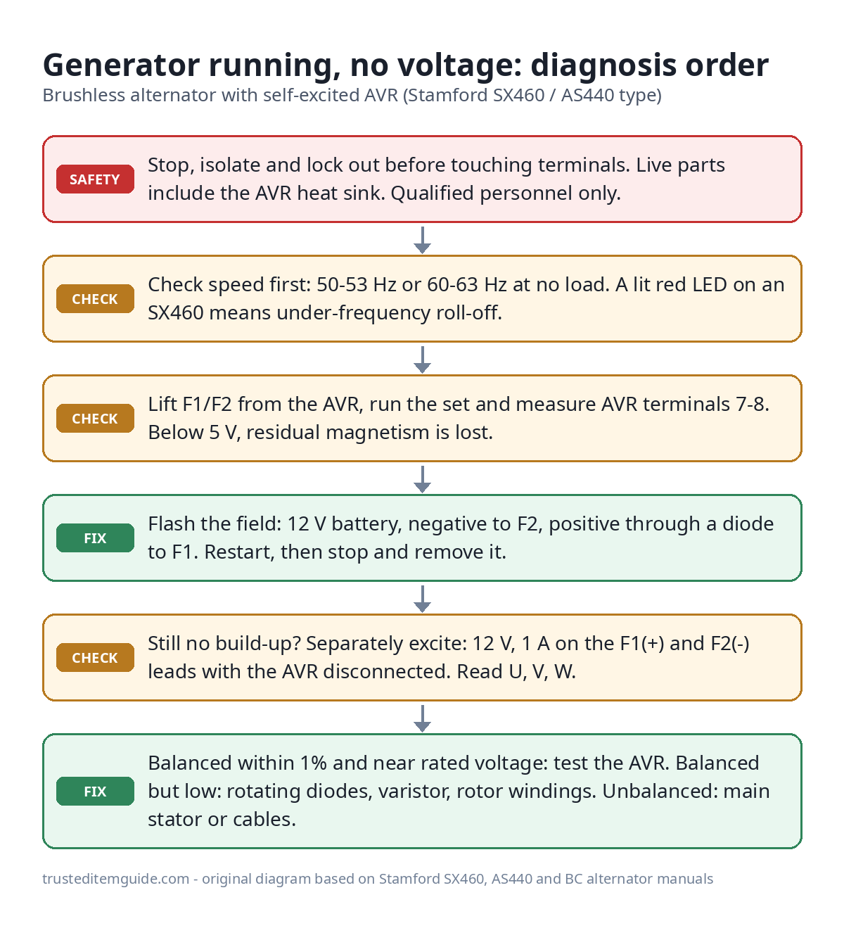
When a generator runs but is not producing voltage, the excitation chain has broken somewhere. On a brushless genset alternator with an AVR, such as a Stamford with an SX460 or AS440, the usual causes, in order of how easy they are to check, are: wrong engine speed; an open breaker, link or connection; lost residual magnetism; a failed AVR; or a failed rotating diode, varistor or winding. A few measurements tell you which.
The short version: confirm the frequency is at nominal. Then lift the exciter field leads (F1/F2) from the AVR, run the set, and measure the AVR sensing terminals (7-8 on an SX460). Stamford asks for at least 5 V there. If you see less, flash the field with a 12 V battery through a diode. If that fails, a separate excitation test with 12 V on the exciter field shows whether the fault is in the AVR or the alternator.
Safety first. Stamford’s manuals warn that the output terminals, the AVR terminals and the AVR heat sink can all be live and can kill. Before removing covers or changing any connection, stop the set, isolate every energy source (including any anti-condensation heater supply) and apply lockout/tagout. Several tests below run the set with covers off: qualified personnel only, with suitable PPE and insulated tools. Leroy-Somer adds that the exciter field may sit at line potential.
How a brushless alternator builds voltage
Magnetism left in the rotor iron induces a few volts in the main stator. That powers the AVR, which feeds DC to the exciter field (stator). The exciter rotor’s AC is rectified by the rotating diodes and magnetizes the main rotor, which induces full output in the main stator. Each link feeds the next, so a break anywhere stops build-up and leaves you with zero or a few volts.
What you need
- A multimeter with diode test (and ideally frequency)
- An insulation tester (500 V for windings; Stamford’s current UC manual uses 1000 V DC for diode reverse tests)
- A 12 V battery, a rectifier diode (Leroy-Somer specifies 3 A or larger) and insulated clip leads
- A 0-12 V, 1 A DC supply and a 60 W, 240 V lamp (or two 120 V lamps in series) for the AVR test
- The alternator’s wiring diagram and its winding-resistance table or test certificate
Step-by-step diagnosis
- Measure at the right place. Read voltage at the alternator output terminals with the output breaker open, not just at an outlet or panel meter. An automatic mains failure controller such as the Datakom DKG-105 displays generator voltage and frequency, but it shows L1-N only, so check all phases with a meter. Zero, a few volts and “low but present” point to different faults.
- Check speed. Stamford’s fault table checks speed first. The SX460 has under-frequency roll-off (UFRO): below about 95% of nominal frequency it lowers the voltage in proportion to speed, and its red LED lights. Set nominal speed at no load (Stamford gives 50-53 Hz or 60-63 Hz) before judging the alternator.
- Inspect the wiring with the set locked out. Look for loose, burnt or broken connections at F1/F2 (X/XX), the sensing leads to 7-8, and the 1-2 link, which must be fitted if there is no hand trimmer. Stamford’s table points to a broken 1-2 link or trimmer lead for low no-load voltage. Leroy-Somer lists an open regulator, breaker or fuse as a no-voltage cause, so check any AVR supply fuse too.
- Check residual voltage. With the set stationary, remove F1 and F2 from the AVR. Start the set and measure across AVR terminals 7-8. Stamford’s BC alternator manual needs at least 5 V there. Below that, stop the set and flash the field.
- Flash the field. Reconnect F1 and F2 to the AVR. Clip the battery negative to terminal F2 and the battery positive to F1 through the diode. Stamford says the diode is required to protect the AVR. If you use the set’s own starting battery, disconnect the main stator neutral from earth first. Restart: output should come up close to nominal, or 170-250 V at terminals 7-8. Stop, remove the battery, restart. If it now builds up on its own, residual magnetism was the problem.
- Separately excite the alternator. If flashing didn’t work, leave F1/F2 disconnected from the AVR and connect the 12 V, 1 A supply to the field leads (positive to F1, negative to F2). Run at rated speed with no load and measure U, V and W. Stamford expects them to be balanced and within 10% of nominal.
- Balanced within 1% (and within 10% of nominal): the windings and rotating diodes are good; suspect the AVR (next step).
- Balanced but low: rotating diodes, varistor, or exciter or main rotor windings (step 8).
- Unbalanced: main stator or the cables to the breaker (step 9).
- Test the AVR. Connect the lamp across the AVR’s X/XX (F1/F2) output terminals and turn VOLTS fully clockwise. Keep the 12 V supply on the exciter field leads, then run at rated speed. The lamp should glow, and it should go out when you turn VOLTS fully counter-clockwise. If it never lights, Stamford says the AVR is faulty. Afterwards, turn VOLTS fully counter-clockwise and set up the AVR from scratch. Our SX460 voltage adjustment guide covers the VOLTS, STAB and UFRO sequence.
- Test the rotating diodes and varistor (locked out). Disconnect each diode’s lead at its terminal post. Stamford’s 2023 UC manual calls a diode faulty if its forward drop on diode test is outside 0.3-0.9 V, or its reverse resistance is under 20 MΩ at 1000 V DC. The varistor should read above 100 MΩ; a failed one usually looks damaged. If the varistor is bad, replace it and all six diodes. If any diode is bad, replace all six and the varistor.
- Check winding resistance and insulation. Measure the exciter stator across F1/F2, the main rotor across the rectifier plates, and the main stator sections. Compare with your machine’s table: Stamford allows 10% (the UC table is at 22 °C). For scale, the BC16/18 table lists 18-24 Ω for the exciter stator of AVR-controlled machines and 0.44-1.55 Ω for the main rotor. Disconnect the AVR before any insulation test. The BC manual says not to run the machine below 1.0 MΩ at 500 V.
Symptom, likely cause and next test
| What you see | Most likely cause | Next test |
|---|---|---|
| Low voltage, frequency low, red LED on (SX460) | Engine speed or governor, UFRO acting | Set nominal speed, then recheck |
| Under 5 V at 7-8 with F1/F2 lifted | Lost residual magnetism | Flash the field |
| Builds up with the battery connected, collapses when it is removed | AVR or its connections, open exciter or main field winding (Leroy-Somer R250 table) | Lamp test on the AVR, continuity of F1/F2 |
| Full voltage when separately excited, balanced | AVR | Lamp test, then replace and set up |
| Separately excited: balanced but low | Rotating diode, varistor, rotor winding | Diode and varistor tests, rotor resistance |
| Separately excited: unbalanced phases | Main stator or output cables | Section resistance and insulation |
| Voltage comes up, then collapses (AS440); LED lit or flashing | A protective trip: over-excitation (often overload), over-voltage, or under-frequency roll-off. The manual lists all three. | Check speed and load, stop to reset, then find the cause |
Field flashing is not the same on every machine
Forum advice says “touch a 12 V battery to it”, but documented methods differ, and the wrong one can damage the regulator.
| Machine type (source) | Documented method |
|---|---|
| Stamford, AVR-controlled (BC manual) | 12 V battery, through a diode, to F1(+) and F2(-) with the leads on the AVR; restart, then remove. Lift the neutral-earth bond if you use the set’s own battery. |
| Leroy-Somer R250 AVR | New 4-12 V battery on E+ and E- for 2-3 seconds, polarity respected; battery isolated from earth. |
| Leroy-Somer standard AC generator (US manual) | 12 or 24 V battery to the disconnected EF1/EF2 field leads with the engine stopped, or with the set running through a diode of 3 A or more. |
| Brush-type portable (Briggs & Stratton 030430) | 12 V across brush rectifier terminals J1/J2 with excitation wires #2 and #6 removed; polarity not important; run about 5 seconds. |
| Capacitor-regulated (Mecc Alte S20W) | About 50-230 V AC across the capacitor terminals for an instant (not the DC battery often suggested online). Mains-level voltage: a qualified technician’s job. |
Don’t mix procedures across brands. Leroy-Somer’s R250 manual warns that running with the E+/E- circuit open damages the AVR, yet Stamford’s residual check runs an SX460 machine with F1/F2 lifted. On an R250, use its battery test instead.
The thresholds also vary. Stamford’s SX460 and AS440 manuals give a 4 VAC build-up voltage, while its BC alternator manual uses 5 V as the pass mark at terminals 7-8. Our SX460 overview lists the regulator’s specifications. Leroy-Somer says residual magnetism can be lost after a momentary reversal of the field connection, a strong opposing magnetic field, or a long time out of service.
Small portable generators: brushed and capacitor types
Start with the owner’s manual checks. Generac’s GP-series and Honda’s EB2500X manuals list the circuit breaker, the GFCI receptacle and the connected equipment (Generac adds the cord set) before any internal fault.
Brush-type units feed the rotor through carbon brushes and slip rings from a small rectifier or regulator. Briggs & Stratton’s manual for its 5500 W model 030430 says to flash the field below 1 VAC at no load. If that fails, unplug the control panel harness and measure the stator power leads: about 120 V there puts the fault in the panel. The carbon brushes break easily.
Capacitor-regulated units have no AVR and no brushes; a capacitor on an exciter winding in the stator does the regulating. Mecc Alte’s S20W manual lists low speed, a faulty capacitor or faulty windings when the alternator won’t excite. Westerbeke’s guide for its capacitor-excited BC sets adds a quick check: with the capacitor unplugged at no load, about 3-4 VAC line to neutral shows the main stator winding is intact.
Common mistakes
- Replacing the AVR before checking speed and residual voltage
- Flashing an AVR-controlled machine without a diode, or with the output breaker closed
- Using the set’s battery without lifting the neutral-earth link
- Turning VOLTS up on a dead machine; it can’t fix build-up, and Stamford’s setup starts with VOLTS fully counter-clockwise
- Running a Leroy-Somer R250 with E+/E- disconnected, which its manual says damages the AVR
- Running an insulation test with the AVR connected
- Replacing one rotating diode instead of the full set and the varistor
Frequently asked questions
Can a bad AVR cause zero output?
Yes. The AVR supplies all of the exciter field current, so a dead AVR means no build-up. Confirm it with the separate excitation and lamp tests before buying one.
How do I know residual magnetism is lost?
With F1/F2 lifted and the set at rated speed, measure the AVR sensing terminals. On a Stamford machine, under 5 V at 7-8 means you need to flash the field. If flashing restores normal build-up, that was the cause.
Is it safe to flash the field while the generator runs?
Stamford and Leroy-Somer both describe flashing with the field connected to the regulator and the set running, but only through a diode. Leroy-Somer’s no-diode method is for disconnected field leads with the engine stopped. Keep the output breaker open either way.
When to call a technician
Call one if the separate excitation test shows unbalanced phases or low insulation resistance, or if you aren’t trained to work near live terminals. First record the frequency, the residual voltage at 7-8 and the separately excited U-V-W readings. Sources: Stamford’s SX460 and AS440 AVR manuals, the UC alternator owner manual, the BC alternator manual, Leroy-Somer’s R250 AVR and standard AC generator manuals, the Mecc Alte S20W manual, Briggs & Stratton’s 030430 service manual and Generac’s GP-series owner’s manual.