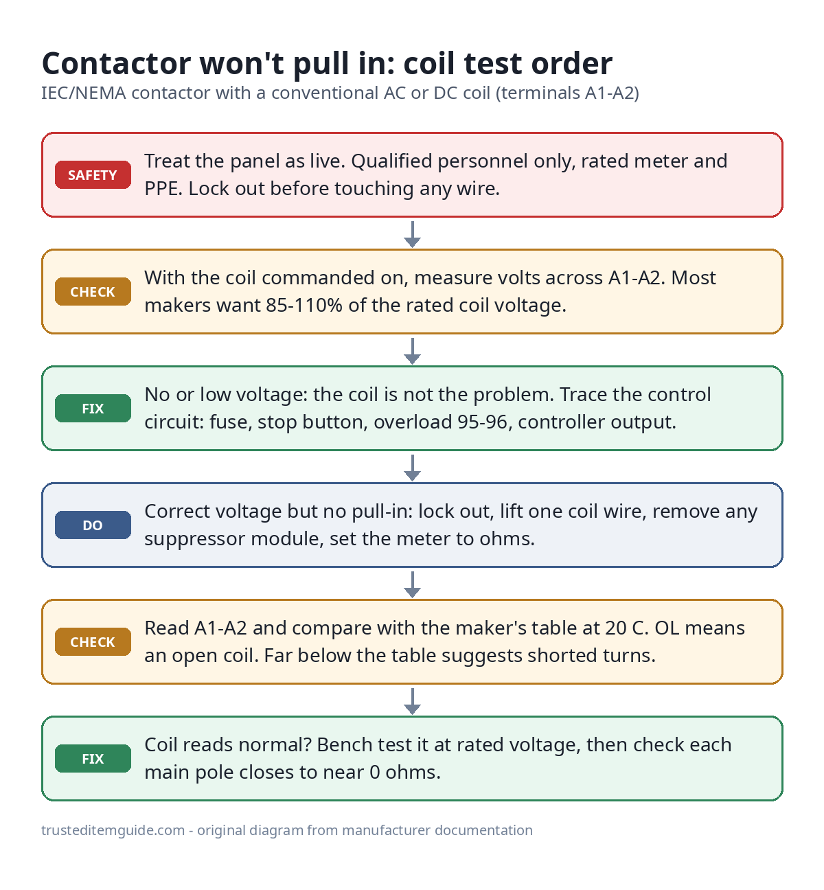
To test a contactor coil with a multimeter, do two checks in this order. First, with the coil commanded on, measure the voltage across terminals A1 and A2. It should be close to the voltage printed on the coil. Second, lock out the circuit, disconnect one coil wire, and measure the resistance across A1-A2 in ohms. OL (open line) means the winding is open and the coil is dead. A reading of zero, or far below the manufacturer’s figure for that exact coil, points to shorted turns. Anything close to the published figure means the coil winding is fine and the fault is elsewhere.
The part most guides get wrong: there is no universal “good” range of ohms. Coil resistance depends on coil voltage, AC or DC, and contactor size. Sprecher+Schuh’s table for its CA7 range lists its healthy 24 V AC coils at 4.55 to 5.05 Ω on the smallest frame and 0.75 to 1.05 Ω on the largest, depending on the coil version. The same table shows a 480 V AC coil at 1,895 Ω. A rule like “under 10 Ω means shorted” would condemn good coils. Compare against the table for your part number, not a generic range.
Safety first. Contactors sit in panels with exposed mains and motor terminals, and the coil circuit may be fed from a separate control supply that stays live after the main breaker is off. The voltage check in step 2 is a live measurement: qualified personnel only, a meter and leads rated for the panel’s measurement category, and suitable PPE. For every resistance test, isolate all supplies, apply lockout/tagout and prove the circuit dead with a tested meter before you touch a wire.
Why the ohms reading looks so low on AC coils
An ohmmeter measures only the DC resistance of the copper winding. In service, an AC coil’s current is limited mostly by its inductance, which is much larger once the armature has closed. Schneider Electric’s data for the TeSys D LC1D09 shows the effect: the coil draws about 70 VA at the moment of closing and only about 7 to 7.5 VA once sealed. If a 24 V coil draws 7.5 VA, that works out to roughly 0.3 A, an impedance of about 77 Ω. The copper resistance the meter sees is only a small part of that.
Two consequences follow. A healthy AC coil can read just a few ohms, so a low reading alone does not prove a short. And you must never feed an AC coil from a DC supply of the same voltage. With no inductive reactance to limit it, the current is set by that small resistance alone and the coil overheats.
What you need
- A digital multimeter with AC/DC volts and ohms, rated for the panel (CAT III or CAT IV where the panel requires it)
- The contactor and coil part numbers, read from the coil itself (the coil is often a separate, replaceable part)
- The manufacturer’s coil data: rated voltage, operating limits and, if published, a coil-resistance table
- Lockout/tagout devices and the panel’s control wiring diagram
- For a bench test: a fused supply that matches the coil’s voltage and type (AC or DC)
Step-by-step: testing the coil
- Identify the coil. Read the voltage and type on the coil, not on the contactor’s main rating plate. Schneider’s coil codes are a good example: B7 is 24 V AC 50/60 Hz, BD is 24 V DC, U7 is 240 V AC. Codes such as BNE (24-60 V AC/DC) mark wide-range electronic coils. Those need the separate treatment described below.
- Measure the coil voltage while it is commanded on. Set the meter to AC or DC volts to match the coil. Probe A1 and A2 while the start button, controller output or thermostat is calling. IEC 60947-4-1 requires a contactor to close between 85% and 110% of its rated control voltage. Rockwell’s IEC contactor data specifies pick-up between 0.85 and 1.1 times the rated control voltage for AC coils and 0.8 to 1.1 for conventional DC coils. Schneider allows -20%/+10% on single-frequency TeSys D AC coils. That is wider than the IEC window, so use your own contactor’s data sheet. Below that window the contactor may fail to close or may chatter.
- No voltage at A1-A2? Stop testing the coil. The fault is upstream: a blown control fuse, an open stop button or limit switch, a tripped overload relay, or a controller that is not switching its output. On IEC overload relays the normally closed contact wired in series with the coil is 95-96. A trip opens it and drops the coil. In a generator transfer panel the coils are often switched by the controller’s relay outputs, so an automatic mains failure module such as the Datakom DKG-105 belongs on the list of suspects.
- Voltage is correct but nothing happens? Lock out and isolate the coil. Switch off the control supply and the main supply, apply lockout/tagout, and prove both dead. Then disconnect at least one wire from A1 or A2. Fluke points out that any parallel path lowers a resistance reading, and a coil still wired into its control circuit has parallel paths. Unplug any suppressor module (RC, varistor or diode) fitted across the coil as well.
- Measure resistance across A1-A2. Set the meter to ohms and touch the probes together first. Fluke notes that test leads typically add 0.2 to 0.5 Ω, which matters on coils that read a few ohms, so use the meter’s REL function to subtract it. Keep your fingers off the probe tips, because your body becomes a parallel path.
- Interpret the reading against the maker’s data. Sprecher+Schuh’s guidance is simple: you should see neither zero (a short) nor infinity (an open circuit). For a closer verdict, compare with the published value. Schneider quotes its coil figures at 20 °C with roughly ±10% tolerance. If the coil has just been running, let it cool first. Copper resistance rises by about 0.4% per °C, so a coil at 60 °C reads around 16% higher than its 20 °C figure.
- If the coil reads normal, bench test the contactor. With the contactor removed, or with its load side fully isolated, apply the rated coil voltage from a fused supply of the correct type. It should close firmly and stay closed without loud humming. With nothing connected to the main terminals, measure across each main pole in ohms: a normally open pole should read OL with the coil off and close to 0 Ω with it energized. A1-A2 is live during this check. With a 120 V or 240 V coil, treat the bench setup as live work and keep your hands clear of the coil terminals.
Real coil resistance figures from manufacturers
These values come from manufacturer documents and show how widely healthy readings vary. They are not interchangeable between brands or series.
| Contactor / coil | Coil voltage | Published resistance | Source note |
|---|---|---|---|
| Sprecher+Schuh CA7-9 (smallest frame) | 24 V AC | 4.55–5.05 Ω (by coil version) | CA7 coil table, 2014 |
| Sprecher+Schuh CA7-97 (largest frame) | 24 V AC | 0.75–1.05 Ω (by coil version) | CA7 coil table, 2014 |
| Sprecher+Schuh CA7-9 | 120 V AC | 115.9 Ω | CA7 coil table, 2014 |
| Sprecher+Schuh CA7-9 | 480 V AC | 1,895.3 Ω | CA7 coil table, 2014 |
| Schneider TeSys D LC1D09-D38, code BD | 24 V DC | 101.9 Ω | Approx. ±10% |
| Square D 8910 definite purpose, coil 9998DA3V14 | Code V14 (check coil label) | 0.654 Ω | ±10% at 20 °C |
The pattern is consistent: higher coil voltage means more turns of finer wire and higher resistance. A bigger contactor at the same voltage needs a stronger magnet and reads lower. A DC coil reads far higher than an AC coil of the same voltage, because its resistance is the only thing limiting its current.
Coils that an ohmmeter can mislead you on
Electronic and wide-range coils
Many current contactors use electronically controlled coils that accept a voltage range, often AC or DC (Schneider’s BNE, EHE and KUE codes are examples). Sprecher+Schuh also lists DC electronic coils for its smaller CA7 frames. The ohms reading across A1-A2 on these is the input of a small electronic circuit, not a bare winding. It will not match a simple resistance figure. For these coils, rely on the voltage check and a bench pull-in test, and use the manufacturer’s data sheet for anything else.
DC coils with two windings
Larger DC contactors often use a strong pull-in winding plus a hold winding that is switched in after closing. Sprecher+Schuh notes that the resistance with the coil fully energized is much higher than the reading at rest, because both windings are then in circuit. Its 48 V DC table makes the point: 764.8 Ω for CA7-60D to 85D but 7.20 Ω for CA7-90D to 97D. Read the right line of the table.
Symptom, likely cause and next test
| Symptom | Likely cause | Next test |
|---|---|---|
| No voltage at A1-A2 when commanded | Control fuse, stop/limit switch, tripped overload (95-96 open), controller output | Trace voltage through the control circuit from the supply to A1 |
| Correct voltage, no pull-in, coil reads OL | Open (burnt) winding | Replace the coil with one of the same code; find why it failed |
| Correct voltage, no pull-in, coil reads near published value | Mechanical binding, wrong coil type (AC vs DC) or electronic coil fault | Bench test; check the coil code against the supply |
| Coil reads zero or far below its table value | Shorted turns | Replace the coil; check that the supply is not above 110% of rating |
| Contactor chatters or hums loudly | Voltage below the pick-up limit, or a sagging control supply | Measure A1-A2 at the moment of closing, when inrush is highest |
| Coil overheats or burns out repeatedly | Wrong coil voltage or type, or sustained overvoltage | Compare the coil marking with the measured supply |
Common mistakes
- Using a generic ohms range. A 24 V AC coil reading 4 Ω may be perfect. Check the maker’s table.
- Measuring with the wires still connected. Parallel paths through the control circuit or a suppressor give a false low reading.
- Replacing the coil without asking why it failed. Overvoltage, the wrong coil and chattering on low voltage all destroy coils. Check the supply before fitting a new one.
Frequently asked questions
What should a contactor coil read in ohms?
Whatever the manufacturer lists for that coil, within about ±10% at 20 °C. Published values for healthy coils range from under 1 Ω (large 24 V AC contactors) to nearly 1,900 Ω (a small 480 V AC coil). Only OL or zero is a clear fail without the table.
Can I test a contactor coil without removing it?
You can check the voltage at A1-A2 in place, which is often enough to find the fault. For an accurate resistance reading, disconnect at least one coil wire and remove any suppressor module so nothing else is in parallel.
How do I test a contactor for continuity?
With the circuit locked out and the load side disconnected, measure across each main pole (for example L1 to T1). A normally open pole should read OL with the contactor released and near 0 Ω when it is closed. A pole that stays high when closed has worn or pitted contacts.
Why does my contactor hum or chatter?
The most common cause is coil voltage below the pick-up limit, often around 85% of rating, especially during the inrush when the coil draws its highest current. Measure the voltage at the moment of closing, not only once it is held in.
Is a coil that reads correctly always good?
Usually, for a conventional winding. A correct reading rules out an open or heavily shorted coil, but not mechanical binding or a fault inside an electronic coil. A bench pull-in test at rated voltage settles it.
Quick checklist
- Read the coil’s voltage, type and code, not the main rating plate.
- Measure A1-A2 while commanded: is it within the pick-up window?
- No voltage: fix the control circuit, not the coil.
- Lock out, lift a wire, remove the suppressor, zero the leads, read ohms.
- Compare with the maker’s table at 20 °C. OL is open, zero is shorted.
- Bench test at rated voltage before condemning a coil that reads normal.
If the contactor feeds a generator or transfer panel and the output is missing even though the contactors close, the problem may be upstream at the alternator. Our guide to a generator not producing voltage covers that diagnosis. Sources: Sprecher+Schuh CA7 coil resistance, Schneider TeSys D DC coil resistance, Schneider TeSys D coil tolerance, Schneider 8910 coil resistance, Schneider coil voltage codes, Schneider overload relay terminals, Fluke: how to measure resistance.